Sunday, February 24, 2019

December 30th  2105

Hmmm. Done it again.


Bought a cheap car to fettle, a little bit.
Rob Winder's Cap (no 03) was sitting in his garage in Kendal. Rob has had it for about 3 years but a new daughter and another new sprog on the way (as well as a new home) meant that he was being distracted from the important business of running his car.

I knew the car (I looked at it before I bought my original Concord) but at the time I thought I couldn't get into it. That was merely a lack of appreciation of the finer points of cramming into a trials car.
Rob had been using it regularly and had changed it's appearance quite a bit. That's him at the top of the blog.

It looked like this when I first saw it, when Mike Salton was running it.


My plan was to do as little as possible, so that I didn't add much value. Then I could justify doing events now and then, as I don't much like the cold and wet events.
I seem to attract the snow somehow, and the wind. Oh! and the rain.

The Raybax, my last car, went Darn Sarf as I had had a belly-full of getting proper wet and cold. It stood me at more than I was happy with so it had to go.

The idea with this one is to keep it much as it is. Just go around it and repair or replace anything that it needed. 
It's running a 1040cc Imp engine. The Concord I bought originally had the same and despite the slight imbalance created by my passenger, it seemed to crawl up hills until my ham-fisted foot caused the wheels to spin. I have learned a bit more about feathering the right foot now and need to learn more about specific techniques to overcome various obstacles.
I fitted a 1600 Suzuki engine to the Concorde and whilst I enjoyed doing it and actually did it for little cost, as the Imp engine sold for a decent price, I think I may have wasted my time. The extra torque was merely a way to spin the wheels earlier.

I don't have a suitable trailer at the moment. I do have a braked trailer which needs to be a little bit longer, but it isn't long enough at the moment. Rob delivered the car using his trailer and I shoved it in the garage ready for a bit of inspection work.


I knew the exhaust manifold was completely knackered, but I built a new one for the Concord, so that isn't a problem.
I decided to strip out quite a lot of stuff Rob had put in. The ballast at the back, a built-in tyre pump, the footboard for the passenger. The wiring is added to in the way most cars that are a bit old seem to become. That needs a new loom making. The oil pressure gauge didn't work. The central "console" is superfluous, and the yellow stars are not really my thing. 


Then I began finding other things which could do with attention. The steering column had a bit of slogger at the top, There was a clunk when wobbling the front wheels (looks like a knackered rose-joint). There was an expansion tank on the cooling system actually in the cockpit, the rear axle pinion oil seal was trashed, the A-frame arms were corroded.


Oh. It could do with a sumpguard. It seems to have lasted quite well without one, but my driving style requires lots of underbody protection.


So, there is a bit to do really. 

I did get an oil pressure gauge from ebay for £15 which I fitted (luckily I had a thread adaptor from a previous installation I had done). I started the engine and had great oil pressure..... Then I didn't..... Then I did..... etc. etc.
I assumed the pressure relief valve was sticking so removed that and cleaned it up. According to the book of words you're supposed to do it annually. These old-fashioned engines, eh?


That's one little job done.

But you didn't think it would end there. Did you?

I know that the car has been a bit troublesome with the fiddle brakes. 

Rob had had a new fiddle brake lever assembly made by a club member, which looked really good, and were in fact the same as on the Raybax (same source).


However he had re-used the master cylinders, which were 0.70" bore and also had a remote reservoir feeding both cylinders. I don't like complexity.
I ordered two new master cylinders with 0.625" bores and integral reservoirs. Less pipery and as the piston moves less fluid the levers move further to get the same braking effect. This effectively means that it is easier to apply the brakes and they are more progressive.

The brakes themselves were a bit more needy.


I thought the discs could do with skimming, but when I took them into my engineering friend's workshop he hid behind his lathe. Seems it's an awkward job. Still, he did me a favour as he lent me a reference book and I identified the brake disc part number. Looked on ebay and got a new pair, post free, for £10.69.

The calipers are fine after a good clean up. The brake pads had come off their backing plates.


Some new EBC pads should make the bite better. (The same change of pads worked wonders on the Concorde. Some people reckon they aren't up to much. I spoke to the bloke who designs the pads and he explained Green Stuff pads are the most suitable. They are designed for low temperature with good initial bite at low speeds. He reckons they work well on trials bikes).

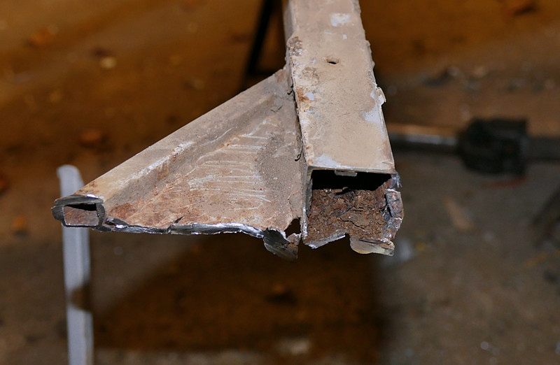
It was whilst I was floundering around cleaning up the mounting plate for the lever assembly that I noticed some corrosion on the chassis rail.

Removing the alloy side panels revealed all. More of which later.......


Saturday, February 23, 2019

Feathery bits in the chassis

February 14th 2016

Yes,  the worm has got a hold.

I took off the side panels and discovered the main 1" square steel tube chassis rail on the driver's side was not as solid as I would have preferred.  In fact it was a bit wooly around the front suspension mounting points as well.
This needed some deep thought.....

I had already removed the back axle and done some work on that (more of that in another post) so I was well on the way to being past the point of no-return anyway.
When I say point-of-no-return I don't mean giving up, I mean either just fettling the odd bit enough to run the car, or fixing everything that I see wrong.

This was the car with the rear side panel removed


Closer examination proved a little worrying


Being very brave, and not crying, I chopped the chassis rail out (after chocking up the chassis and taking a few measurements).


You can see some 1" square steel tube (16 gauge) on top of the car. I needed about 6 ft, but had to buy 20ft. 
Boo.

The rail turned in two directions which I had to cut and weld up before fitting.


The end of the main crossmember was a bit sorry as well, so I had to sleeve it to connect the new rail.


I dealt with the front suspension mounts by plating the existing points rather than start from scratch


Then I cleaned up the tree slider and welded that back on. The front end of it had been made from square steel tube, (this is the passenger side as it happens but both sides are getting the treatment)


I replaced that with round tube, to look better.


If you are sharp-eyed you'll see that I also lowered the top rail by 2.5" This is purely to make it easier to get in and out of the car.
Then I re-attached the mounting plate for the fiddle brakes, but reduced in size so that it just supports the lever assembly.


Next. 

I got around to taking of the tree slider bar on the passenger side to alter the front end as on the driver's side.

"Ah!"

The bottom chassis rail on that side wasn't too clever either. Not as feathery but certainly with some rusty bits. I should have guessed that someone wouldn't have bothered tacking dirty great angle-iron pieces on each side just for fun..... There was also a big crack through the chassis tube at the bottom of the upright that the shocker is mounted on.


So out with the cutting disc again and a repeat of the driver's side replacement.
I also lowered the top rail for the sake of symmetry and because some of my shorter-arsed passengers seem to have trouble getting their leg over.

Now in the chop-and-replace frame of mind I took against the crossmember in the "boot" area. It helps support two batteries and locates the panhard rod. Again someone had made merry with the welding stick and stuck on a bit of angle-iron on. So it had to go.
What a good job I had to buy all that steel tube!

This was underneath looking at the crossmember, just above the panhrad rod.


Whilst I was at it I replaced a bit of the rear crossmember (rust) and the top rail of the "boot" area with it's strut. Someone had made a triangulated plate to stop it twisting, as the spare wheel was mounted on it. This would make the new alloy rear panel an awkward fit and, as I was going to mount the spare on the roll over bar, it didn't matter.
I also put some new diagonals from the rear up to the top rail as I wondered if the spare wheel and batteries had had a hand in creating the cracks in the chassis. Lots of weight bashing down when the suspension bottoms etc.

This was the scene of the crime.


... and this was the rear compartment without, and then with, the diagonal.


I'm not sure it will make any difference, but it cost nothing, weighs nearly nothing, so it doesn't do any harm, and may help.
I have to keep reminding myself that any faults I find have taken up to 40 years to appear, so this is more a question of doing a thorough job than expecting anything to go wrong anytime soon.


That's enough for now. 

I'll detail the work on the rear axle and the steering wheel hub next time


Friday, February 22, 2019

Those bits I mentioned earlier

February19th 2016

It's getting a bit out of sequence. Not that it makes much difference. I didn't have a Master Plan.


The Steering Wheel

When I got the car the wheel looked a bit odd. It turned out it was spaced away from the column with bolts and nuts in piles.
What a bloody awful description. Look at the piccy....


I'd already decided that it needed to be a bit further away still as I have more leg than body and my knees were in the way. The top bearing had a fair bit of slogger in it, so a dismantling was in order. 
If I was a beer can aficionado I could probably have dated the top bearing repair as it had been shimmed up with a chopped up Black Label beer can. 

I got a new oil-less bush and fitted that to remove the free play and then worked out how to make a taller boss for the wheel. Looking on t'internet they were about £35 upwards so a home brew affair was called for.
I use a cheap MIG welder with those disposable CO2 bottles, so I chopped the end from an empty one (the tape is to give me a decent guide-line for cutting with an angle grinder)


Then I welded it onto the top of the column (using a stick welder) and ground it down, all pretty-like.


That fitted in the bushes fine and I could test the length for knee-proximity. I'd allowed spare, but it looked like I would need it all.
I welded a flange on the top and a quick coat of silk black made it all wonderful. No play, no sticky-out bolts and a decent start to the work.


Back Axle

I took the axle off meaning to leave it until later. However I did want to know what sort of diff it had in. We had measured at at about 5.8(ish):1 by marking the prop flange and a tyre and pushing it along the garage, counting the prop rotations.
But I didn't know if it was a twin pin diff or not.

So I cleaned the axle up....


...and took the diff out.

The A-frame arms looked a bit worse for wear. They seemed to have been modified in the past, with some bumpy-looking welds. I cleaned the welds up, ground them out a bit and re-welded them.


The front oil seal was torn to shreds. It looked like bracken had got into it. I had taken the flange off, thinking I would need to set the diff up again anyway.


It turned out to be a single pin diff. Apart from the "growths" on the bearing caps it was in really good nick. The gears hardly seemed run-in.
A tooth count came up with 35 on the crown-wheel and 6 on the pinion which works out at 5.83:1.
I would have preferred 6:1 or even 6.16:1, but beggars can't be choosers and that's what it is.


A clean up, new oil seal and re-fit of the pinion flange (my mechanic friend helped and we decided we had just nipped up to the collapsible spacer enough to remove play but not alter the mesh). Time will tell.


A coat of paint and that was ready to fit again, when I had got the chassis sorted out.


Spare wheel carrier

Looking at shots of this car and others on trials (thanks to Glenn Bennett's albums) I thought the spare wheel seemed a bit low and didn't offer much extra head protection in the case of a roll-over.


I decided to fit it higher up and whilst it may slightly raise the CoG, at least if the car did fall over it would be better for protection.


I did this by welding a bit of tube across the roll-over bar stays and putting the bolts that used to be on the body top frame on there.


I added some tubes to the top frame to act as supports beneath the tyre. The wheel doesn't actually bear on them, but in the case of an inversion they would help prevent any further movement if the roll over bar or the wheel mount moved.


Other stuff to do

I'm getting to the "putting back together" stage now and am looking at things like cleaning up the alloy panels. I don't think I'll replace any at the moment. I could always do that later on.

Refitting the fuel line and pump will need a bit of thought with regard to protecting them more (I discounted running it through the chassis top rail) and cleaning up and polishing the alloy tank would be nice. I am altering the cooling system to remove the expansion tank (which had ended up in the cockpit) and will probably move the water pump to the cool side of the engine, drawing water from the rad and pushing it into the block. That would provide room to fit an alternator on the passenger side of the engine and then I could rely on one battery and more cooling fan action.
I've got a new battery cable which is more flexible, so I should be able to protect that more easily in the cockpit.

The exhaust manifold is a pile of rust in a vaguely familiar shape, so that is a new-build really.


There's a new loom to make, a sumpguard and brackets to make and I haven't even looked at the front axle yet. Some new rose joints needed there.
Oh yes. The bonnet needs altering a touch as well.

More next time.........


Thursday, February 21, 2019

Starting to get fiddly now.


April 13th 2016

As you work your way through refurbishing a car you come across bits needing attention, that you store away in the back of your mind until later. Things that need altering to allow you to do something else.

Well I'm starting to catch up on those things now.


Battery Cable

I put the battery cable in a conduit to pass through the cockpit and put the fuel pump wire in as well. However as I plan to get rid of one battery and put an alternator on the car I needed to put a couple of wires in the conduit as a feed and return to the master switch, so that it cuts the ignition when the switch is operated. I did wonder about putting a spare cable in, but couldn't think why I may need it. I crimped new ends on with a great pair terminal pliers I borrowed from a friend. At over £100 it's not the sort of thing you buy for the one use.

Once I'd done this I could fit the floor and seat pans back in.

This is the conduit coming alongside the seat


and then through the front bulkhead


I cleaned up the floor panels and straightened and reinforced the heel rests. It may be they want altering to suit me, but that's a good starting place.


Back Axle Install

I decided to fit the back axle. I wasn't sure about that as it will need to come off again to fit the side panels as the coil shocks go outside the panels. However it made the car mobile again and I wanted to turn it around it the garage so that I could attack the front end.


This is with the passenger seat pan still to be fitted. I left it out so I could do the propshaft nuts up more easily.
I used a body mastic (UPOL Tiger, I think) to bed the floor and seat pans on.
Wow! It's fierce. You don't really need pop-rivets. Still it should help with chassis stiffness.


Now...

The next thing to attend to ...... 

the next two things to attend to ..... 

the next three things to attend to ......  are to move the water pump to the driver's side, fit the alternator on the passenger side and replace the alloy plate engine mounts with something a bit more robust.

Because of where the distributor is it will be tricky to fit the alternator on the driver's side and besides that, I think it will be better to have the water pump on that side. Up until now, it has been taking hot water from the head and pumping it into the radiator top hose.
With it moved to the other side it can take cooler water from the bottom hose and pump it into the engine block. That is the way most cooling systems work. This will mean it is operating with cooler water and stands less chance of getting an air lock.

It's not an Imp water pump, but it is a remote one. It has been created by bolting a machined alloy block to the back of a Mini water pump. This is good because new Mini pumps are easily available for about £15.00.

This is the water pump on the right of the picture. The alloy-plate engine mount on the left will need cutting down to make space for the water pump.


Engine Mount Dilemma

However, as usual, when I removed the engine mount I discovered a problem. The studs that the mount are bolted to pass through the timing case cover, but the threads are in the engine block. This means about 2" of the studs are unsupported and years of bashing and crashing have cracked the bosses in the timing case cover.


It isn't a problem as far as the timing case is concerned. All the nuts have to do is clamp it up against the face on the engine block. But I can't carry on yanking them about as they had been when doing service as engine mount locators.

This is not the end of the world as the middle engine mount (rather oddly there is one front engine mount and then one on the other side at the back of the engine block, then one under the gearbox tailshaft) is also an alloy plate on the bell-housing and I have my doubts about the strength of that as well.


Right: New plan. 

Ditch the old mounts and build some new ones using the original and "proper" engine mount bosses on the crankcase. I can connect them to new uprights which I'll fit to the chassis frame.
A vertical tube attached to those three tapped holes in the block, and extending down to the bottom of the sump, will give me a good engine mount and a sumpguard mount into the bargain.


So this is the mount. I made it from 16 gauge steel tube (the same as I used for the chassis repairs) which isn't the strongest available, but stronger than the flimsy alloy plates used before. I fixed a new piece into the chassis frame for the engine mounted part to bolt to.


This shot from the rear. I capped the tops of the tubes to avoid mud and water getting trapped. The engine was chocked before removing the old mounts and my hope is it will stay in the same spot when the new mounts take the strain. The leg going downwards is to fit the sumpguard to.


I did the same on the driver's side. 


I took the first of these shots before removing the chocks under the sump. The straight edge is just level with the the top of the bolt head at 26.5cms.


This second shot is after removing the chocks, with the engine now supported by the new mounts. 
Just the same! It hasn't dropped at all. I took the opportunity to move the engine sideways half a centimetre to avoid contact with a front supsension arm that had been happening. 


Water Pump

A previous owner who had put on the Mini water pump had used one with a by-pass hose outlet. This had fugly bit of hose with a bolt stuck in the end to block it off. You can get pumps with the by-pass take-off blocked now, so that will tidy up the installation.


The machined alloy block on the pump has a steel plate on the back with the outlet pipe. It needs chopping and turning, but what's new?
The pulley is wrong and puts the pump too far back in the engine bay, interfering with the HT leads and such. I got a proper A series pulley which has a 2" offset back towards the pump body. This allows me to move the pump forwards, but I'll have to move the radiator as well to clear the front boss of the pump.


Using the original  bracket on the chassis that the discarded engine mount had been fitted to I mounted the water pump. It won't have any adjustment and is mounted solidly to the chassis rails. The engine should not move enough to throw the belt. The belt will drive both the pump and the alternator, at the other side of the engine, which will provide the adjustment to tighten the belt..


This is just a initial installation as I will be fitting a new pump to the alloy backing plate. Getting the pulleys lined up takes a bit of doing. Using a straight edge and packing the mounts with washers allows me to get it just about spot on.I deliberately left the brackets needing packing. If you plan to get the brackets in the right spot without packing washers then discover it isn't, you may have to cut the brackets off the chassis frame and start again.
The outlet on the back of the pump had a 90 degree bend in it. It faced the wrong way.
I thought that if I had a straight outlet I could use hose bends to get the path right to connect to the engine. To do this I got my engineer friend to cut the old pipe off and TIG weld a new, stainless bit of pipe on. If I had used steel I would have done it with MIG. But his welding is much better than mine.
 Because it is a Mini pump the inlet is facing the wrong way really. I will overcome that with silicone hoses and some copper tube. If the distributor hadn't been there I could have inverted it to make it much simpler.


The new pump, alloy block and backing plate


Assembled


Making a bracket for my new alternator.

eBay came up with a great Denso competition alternator that's only 40 Amps, but very compact. It looks like I'll just have to ditch the electric windows and air-con. But you have to make some sacrifices in this game.


I made a bracket that used 2 timing case studs across the front on the engine to make a pivot for the alternator.  The adjuster stay is fixed to the chassis frame. So I hope the new engine mounts hold everything steady!


Again getting all three pulleys aligned took a while, but I got there. I did use a straight edge, honest.


I'll finish this post now as the front axle is the next item and that is a story in itself............